The structural analysis software RFEM 6 is the basis of a modular software system. The main program RFEM 6 is used to define structures, materials, and loads of planar and spatial structural systems consisting of plates, walls, shells, and members. The program also allows you to create combined structures as well as to model solid and contact elements.
RSTAB 9 is a powerful analysis and design software for 3D beam, frame, or truss structure calculations, reflecting the current state of the art and helping structural engineers meet requirements in modern civil engineering.
Do you often spend too long calculating cross-sections? Dlubal Software and the RSECTION stand-alone program facilitate your work by determining section properties of various cross-sections and performing a subsequent stress analysis.
Do you always know where the wind is blowing from? From the direction of innovation, of course! With RWIND 2, you have a program at your side that uses a digital wind tunnel for the numerical simulation of wind flows. The program simulates these flows around any building geometry and determines the wind loads on the surfaces.
Are you looking for an overview of snow load zones, wind zones, and seismic zones? Then you are in the right place. Use the Geo-Zone Tool to determine quickly and efficiently snow loads, wind speeds, and seismic data according to ASCE 7‑16 and other international standards.
Would you like to try out the capabilities of the Dlubal Software programs? You have the opportunity to do so! The free 90-day full version allows you to thoroughly test all our programs.
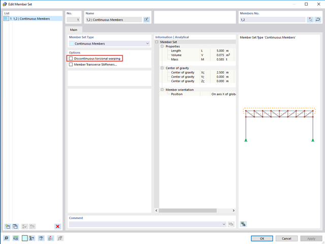
Releases for warping are at each member end by default. Splitting members leads to a warping release.
If you do not want to have a warping release there, but rather continuous warping, you need to define a member set. When activating the "Torsional Warping" add-on, the warping is transferred automatically. If this is not desired for the member set, select the "Discontinuous torsional warping" option; see the image.
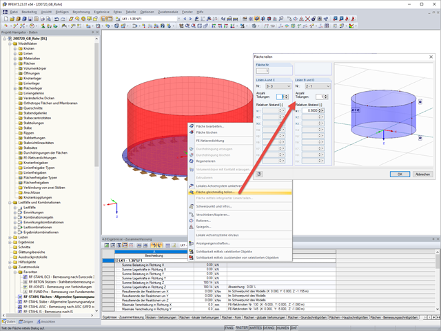
If you have modeled your pipe surface as a quadrangle surface, you can achieve this by splitting the surface at least once.
Then, define a new average region for the surface by selecting the center, defining the dimension, specifying the vector, and determining the averaging type you want.
You can easily define the vector by picking two points.
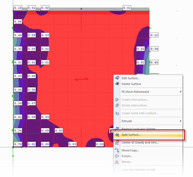
Unfortunately, there is no "Split surface along selected line" feature. You can either split the surface equally or along all the integrated lines.
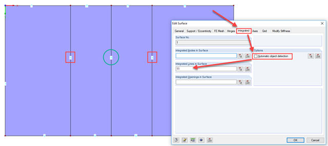
In order to split the surface on one integrated line only, it is necessary to temporarily manage the integrated lines manually (see Image 01). After splitting the surface, you can enable the automatic object detection again (see Image 02).